FSAE Firewall
Design Choices and Implementation
Shortly after joining Penn Electric Racing in 2023, I assumed sole oversight of the firewall. The firewall is a carefully bent sheet of aluminum between the battery pack and the driver to prevent injury in the event of a fire. Through multiple design iterations, I was able to create a superior design that met all requirements, added rain test protection, and improved aero performance. Check out my design process!

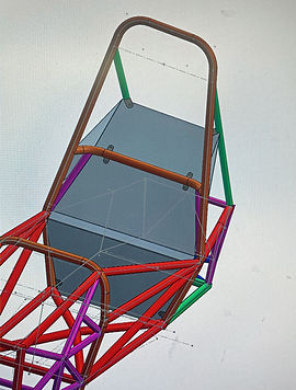
Rules Compliance
I based my first iteration on last year's firewall since team knowledge is a great asset to my design. FSAE rules state that the firewall must fit tightly against the chassis tubes, and between the seat and battery pack. The firewall must block line of sight from the driver to the tractive (high voltage) system and I accomplished this by fully covering all gaps between chassis tubes using the sheet metal feature in SOLIDWORKS. It is also required that the firewall be at least 25mm away from the accumulator as you can see on the right. With a much shorter and lighter chassis this year, the accumulator is very close to the cockpit, so I had to get make educated guesses when bending the main firewall sheet.
Previous Revision's firewall

Final CAD/ Improvements
After ensuring rules compliance, I refined the design of the firewall to fit tighter to the chassis tubes by using the convert entities feature in SOLIDWORKS. It is important to break external references when working in a PDM software with your team. I also made the top sheet of the firewall completely flat rather than angled up as in last year's firewall. The firewall is adjacent to the rear wing and can disturb airflow as seen on CFD for the car. The flatter design not only has the benefit of decreased drag, but also can keep the electrical components dry during rain test.
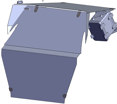
Final CAD
Original CAD
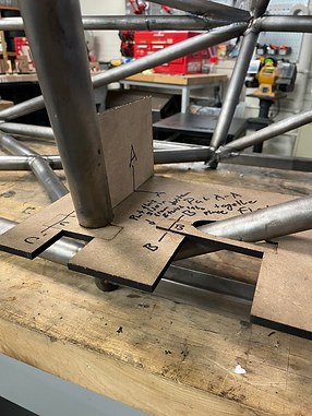
Tabs & Jig Design
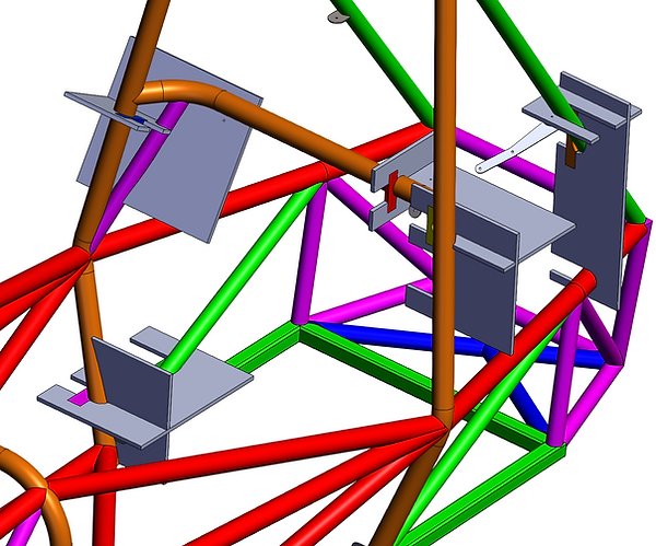
I made tabs for the firewall as seen above that will be welded to the chassis tubes. Since the firewall tabs are not load-bearing, no FEA was required. I used 4 tabs for each of the two pieces of the firewall, so I had 4 unique jigs to design. Since the tabs must be placed precisely when being welded, jigs are required to keep them in place. See my jig assembly to the left. When designing jigs, it is important to think about where the welders will be able to access the weld from. Since I have two tabs that are very close in proximity, I made sure to jig from the side that allows the most free movement for the welders. The convert entities feature is king when designing jigs that will fit tightly to the chassis. It is important to remember that the laser cut pieces of MDF intersect only at right angles, so jigs must be
planned out to maximize anchor points to the chassis. It is also important to remember to covert entities on both sides of the jig or else the space required for the tube will be underestimated. I designed a new way of securing jigs to the chassis by making a rectangular cut in the jig and a corresponding dog bone that has the exact contour of the chassis tube. This grips the tube on all sides and restricts the degrees of freedom much more than a rectangular piece with no cutout. In practice, I was pleasantly surprised when all of the jigs were securely fastened to the chassis on the first attempt.
Jig Implementation